
Revit Add-on módosítása egyszerű grafikus paraméterekkel
Absztrakt: A kutatást a magas részletezettségű épületinformációs modellek piaci környezetben történő alkalmazása indította el. Az építőipar legnagyobb ütemben fejlődő szakága ez, ami ezáltal fontossá és életszerűvé teszi a kutatás jelentőségét. A gépészeti, elektromos és tűzvédelmi rendszerek modellezése a projekt egészét vizsgálva annak nagy időhányadát teszik ki, ez a megállapítás indukálta a kutatás elkészítését. A grafikus parametérek módosítása egy Autodesk Revit add-on esetében támogatja a folyamatok gyorsítását és csökkenti a modellezési hibák számát. Ez a kutatás megmutatja, hogyan érdemes gonolkozni és belevágni a módosítási folyamatokba. A bemutatás részét képezi egy esettanulmány, amely egy valós projekt során mért idő- és pénzmegtakarítási lehetőségeket szemlélteti.
Cikk publikálva: DOI: 10.1556/606.2018.13.3.8, Vol. 13, No. 3, pp. 73–81 (2018)
https://akademiai.com/doi/abs/10.1556/606.2018.13.3.8
https://akademiai.com/doi/abs/10.1556/606.2018.13.3.8
REVIT ADD-ON MODIFICATION WITH SIMPLE GRAPHICAL PARAMETERS
1 József ETLINGER, 2 Olivér RÁK, 3 Márk ZAGORÁCZ,4 Patrik Márk MÁDER
1,3 Department of Engineering Studies, Institute of Smart Technology and Engineering Faculty of Engineering and Information Technology, University of Pecs, Boszorkány u. 2 7624 Pécs, Hungary,
e-mail: 1etlinger.jozsef@mik.pte.hu, 2zagoracz.mark@mik.pte.hu
2,4 Breuer Marcell Doctoral School, Department of Engineering Studies, Institute of Smart Technology and Engineering, Faculty of Engineering and Information Technology, University of Pecs, Boszorkány u. 2, 7624 Pécs, Hungary
e-mail: 2oliver.rak@mik.pte.hu, 4patrik.mader@mik.pte.hu
Abstract: This research comes from the high detailed experience of building information modeling work. This profession is new, but it is a rapidly developing part of the construction industry, therefore this topic becomes relevant nowadays. The mechanical, electrical, plumbing, and fire protection systems modeling take a lot of time in a project and this statement induce the producing of the research. The modification of the graphical parameters of an Autodesk Revit add-on supports the process makes it faster and helps to decrease the number of mistakes. This research will show the method and the way of thinking in case of a modification. A case study will represent the saved time and money in a big project.
Keywords: Building information modeling, Mechanical, electrical, plumbing and fire protection system coordination, Revit add-on, add-on modification, hanger
1. Introduction
The purpose of this paper is to show how to save time and money during the modeling process. Most of the customers are looking for a ‘cheap’ but proficient company. The parametric data in a collaborative model can also save time during the design process and the construction administration phase by improving coordination and reducing the need for additional site visits, printing and manual drawing overviews [1]. If these expectations need to be accomplished, the architects and the Building Information Modeling (BIM) experts have to find new solutions. One of these ideas could be an add-on modification to decrease the working hours. The expert needs to know, which the critical parts of a project are and what the principles are in operation of an examined add-on.
Firstly, the parts of a project are analyzed. The main data is the considered type of the building. Inasmuch the 3D model is made of a detached house then it is too simple to get benefit from the add-on modification, because it has a various element structure and there is no scheme to use. In this situation the modification would be a wasted time. Nevertheless, in case of a commercial building the experts need to find new solutions for the ‘problems’. That kind of building has structural, architectural and Mechanical, Electrical, Plumbing, and Fire (MEPF) protection parts also, which can contain various types of the elements [2]. Usually the customer’s expectation is that the MEPF part to be modeled with them structures for the quantity calculation, for the clash detection or in special cases for earthquake fire simulations [3].
Nowadays the clash detection part of BIM modeling became more complicated and it requires specifying the key areas [4]. The collision detection methods can reduce the potential risk and rework in a project [5]. The difficulty comes when the usage of the BIM technologies will be examined. The study about the current status of BIM adoptability shows, which part of the MEPF systems are most commonly modeled by BIM technology in the USA in 2009. The typically modeled parts are the branch and feeder conduits in 92% of the responses, the seconds are the electrical rooms with 89% and the cable trays and other supports got 86% of responses. The hangers are modeled in 46%, so it needs to be placed at near to the half of the projects in 3D [6]. The case study of this research will represent a decision making process which helped to define the best choice for the required modeled elements in a Hungarian project.
The Autodesk Revit platform was chosen for the modeling process because of the investors’ expectation in the project (case study) and the wide usage and appropriate support of the software. The Autodesk is currently the leadership company and they acquired the Revit Technology Corporation in 2002 [7]. This integration made possible to use a program, which was developed to produce and manage BIM models.
However it takes a lot of time to place the 3D elements manually. Currently for the Autodesk Revit platform 166 MEPF add-ons available, it is to help for the experts [8]. On the other hand these additional programs are not working perfectly and sometimes needs a modification on it. In many cases the computer-aided process can be more effective [9], and if it is combined with human usage and ideas becomes the most profitable solution.
The chosen add-on is the ‘ESoo Support and Hanger 2016’, which helps to place the hangers for the MEPF elements. Before making an add-on modification the experts need to examine the crucial parts of the modeling process. The following parameters are important: distances between the hangers, the positioning, where and how to place the stiffening. The placing rules are depending on the building and environmental conditions, but obviously the different ducts or pipes need another hanger profile. Furthermore the fire safety regulations can modify the planning process of the elements. Numerous types of these objects are available and it makes more complicated to work with them.
If the expectations and every other factor are known, and the add-on is not working perfectly, then the BIM expert has to plan the modification process.
2. Modification
The type of the placing method is a significant part of the 3D modeling. The manually process is useful in most of the cases. Moreover this kind of modeling is more controllable and easier. Nevertheless the usage of an add-on can be appropriate for more complex buildings with different types of the MEPF systems. In consideration of the working method of an add-on can be simple or complex. Some of those are available for free but the most has to be paid for. It was mentioned in the previous chapter that the add-ons are not functional perfectly and in many cases needs to correct the mistakes, which causes extra work and wasted time for the experts.
This research will show a simple add-on modification, but firstly examine the original element’s working rules and methods. The program installed the basic elements and the menu. As it is shown in Fig. 1 this is useful for pipes, ducts, cable trays and conduits with the different forms obviously. The selectable parameters are the layout settings, lowest elevation, the split length and there are few fitting settings also.

Fig. 1. ‘ESoo Support And Hanger 2016’ add-on original settings and elements
The program gets the information from the selected elements directly. The height of the axis, the diameter and the upper plane of the object will be used at the circular systems. In case of rectangular elements the width and the height are taken into account. These dimensions are used for the sizing and positioning the hangers. The problem occurs when more pipes or ducts are placed on one hanger or a round placed on a trapezoid one. As it is shown in Fig. 2 the positioning process of a hanger need 2 steps if the size calculation is perfect. The first step is the dimension changing and the second is the moving process into the correct position.
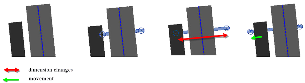
Fig. 2. The ‘problems’ in a specialized situation
Examine the modification, which helps to find an easier and faster way of the modeling process. The aim of the changes is to decrease the time in the complicated cases. Fig. 3 represents the used attributes from the original type of elements. The most of those are applied for the modified elements, because the purpose of the modification is to improve the original elements with small graphical parameter changes. The continuous line connections represent the new parameters, the dash lines highlight the parameters from the rectangular elements, the dotted line represents the used parameter of round elements, and the dash dot lines highlight the used common parameters.
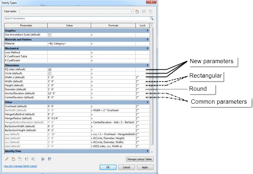
Fig. 3. The used initially parameters of the original elements
2.1. Modification process 1
Explaining of the added and modified attributes and parameters:
‒ Diameter (default): If it is used on circular elements then the add-on fills automatically this parameter. Evidently the diameter of the pipe or the duct will added into;
‒ Circle (default): If the elements are circular then the program uses the diameter parameter evidently, but in case of rectangular forms the width and the height parameters are relevant. The circle attribute can be ‘yes’ or ‘no’. The ‘yes’ option means the using of circular elements and this switcher can select between two values (it is circular or no). Nevertheless for this option functionalization needs 2 another parameter, which are taken into account the status of the circle attribute. These are the ‘bbb’ and the ‘ccc’ attributions;
‒ bbb (default): If the ‘Circle’ switcher is ‘yes’, then it contains the diameter value. In the opposite case the formula will use the height of the rectangular duct. (The formula can be seen in Fig. 4);
‒ ccc (default): This parameter is same as ‘bbb’ nevertheless if the switcher is ‘no’ then it will use the width value for the calculation. (The formula is presented in Fig. 4).
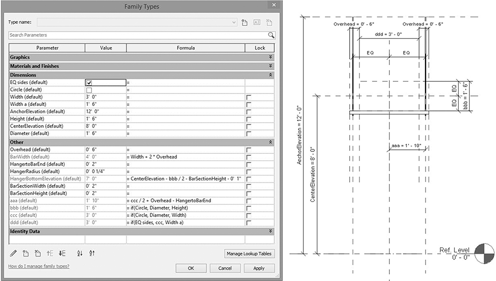
Fig. 4. The modified element structure with the linked parameters and attributes
With the help of these modifications the add-on knows automatically the form of the element (circular/rectangular) and it will use the correct parameter for the placing.
2.2. Modification process 2
The effect of the next modifications is that one side of the element can be fixed till the other side can moving if the size is changing. In case of more elements on one hanger this trick is useful and it can decrease the modeling time largely. It needs some new attributes to reach this working method:
‒ Width a (default): The value of this parameter is freely variable. It needs another attribute for the correct functionalization;
‒ EQ sides (default): This attribute is quite the same switcher as the ‘circle’. If it is ‘yes’ then the program will use the original parameters of the element, but if it is ‘no’ the ‘Width a’ value become relevant;
‒ ddd (default): This attribute is necessary for the correct operation. If the ‘EQ sides’ is ‘yes’, then the value will be the same as the parameter ‘ccc’. Conversely the ‘Width a’ value will be used. (The formula can be seen in Fig. 4).
These modifications make possible to change the width parameter independently of the original element.
The formula of the ‘HangerBottomElevation (default)’ was overwriting also. The ‘Height’ value was changed to ‘bbb’ and it causes that the add-on takes into account the form at the height calculation. The computing of the value needs 2 more extra parameters, which are the CenterElevation and the BarSectionHeight. The first means the (height) position of the middle point and the second means the height of the trapezoid element. In addition, there is a ‘1’ subtraction, which determines the overhanging of the vertical structural parts of the hanger at the bottom.
One more calculated attribute is responsible for the fixed position. It means that during the placing method one side of the element stay in the original position relatively to the pipe or duct.
‒ aaa (default): This formula calculate the position of the rods in case of similar position in the two sides and it is calculated by the width of the element. By using this attribute one side is fixed. (The formula can be seen in Fig. 4);
‒ ddd (default): The size changes follows from this parameter. It takes into account, which value is relevant, the original width or the ‘width a’. With this modification this part of the element is independent from the other part. (The formula is presented in Fig. 4.)
‒ ddd (default): The size changes follows from this parameter. It takes into account, which value is relevant, the original width or the ‘width a’. With this modification this part of the element is independent from the other part. (The formula is presented in Fig. 4.)
Originally the changing of the width parameter causes same differences from the middle line. But now the modification of the two parts of the hanger working separately and this makes the modeling process easier. The modification saves a lot of unnecessary move command. The calculation of the hangers positions working automatically and the experts do not have to make more moves and calculations to find the correct position.
3. Case study
The goal of this modification was to find a way how to decrease the modeling time and the mistakes during the placing process. It was tested in a 1000 m2 area in an office building, which was in ownership of a Telecommunication Company. The whole building is about 130 000 m2 and the costumer would like to know how much time needed for the placing of the hangers. As it is shown in Fig. 5 this area is appropriate for the research because of many, mechanical, plumbing and fire protection equipment. The hangers were placed only on the duct and the pipe systems without cable trays.
The spent time to make this modification was 4 hours. Firstly the modeling was made with the original add-on. On this test area it takes 500 minutes. After that the modified add-on were used, and the time was decreased to 480 minutes. The rate of the reduction is 4.13%. This is not a huge number, but if this value is taken into account for the whole building, than it becomes relevant.
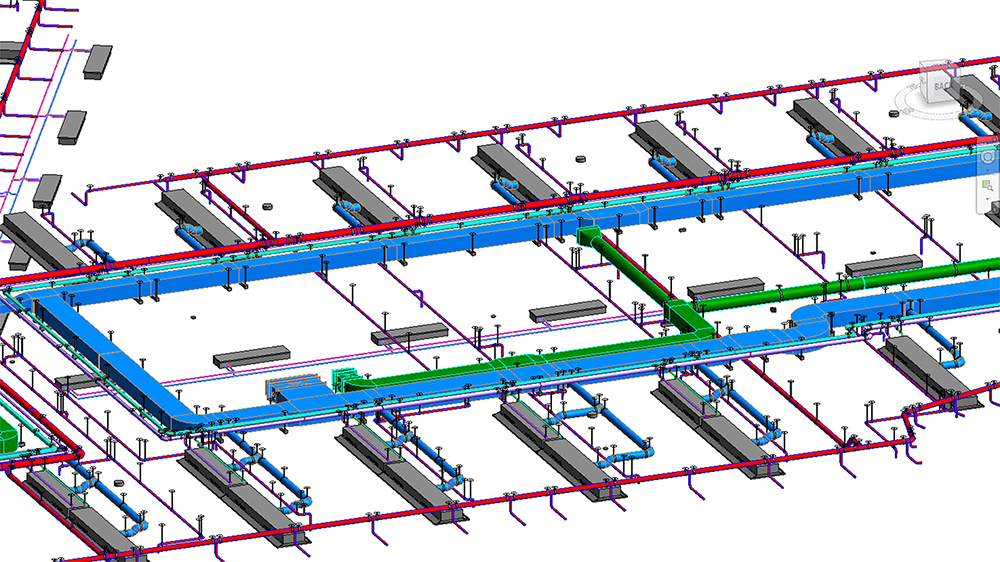
Fig. 5. The placed hanger in the 1000 m2 test area from Autodesk Revit
The whole building is about 130 000 m2 and the tested part was only 1 000 m2 therefore the total construction site is 130 times larger than the test area. The calculation of the total modeling hour’s shows, the modeling time with the original add-on would be 1083.33 hours and with the modified would be 1040 hours. The differences between these two values are 43.33 hours (Fig. 6). To illustrate the decreasing needs to calculate of the costs for this value.
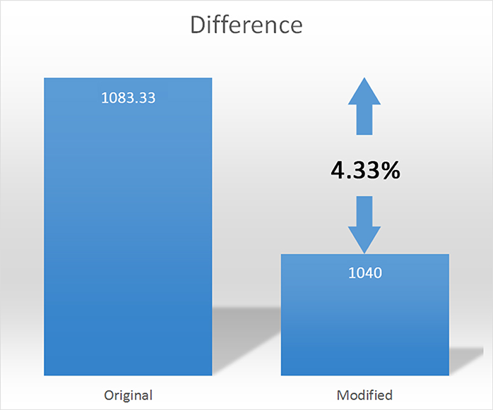
Fig. 6. Comparison of the working hours with the original and the modified add-on
The used cost for the modeling is 20 euros per hour. The producing of the whole building with the original add-on costs 21 666 Euros, but with the modified ones it takes 20 800 Euros. Consequently the saved money is 866 euros, which is not so relevant in comparison with the total costs, but if it is possible to make modifications in the other add-ons then it also could be profitable.
3.1. Remark
The MEPF plans in an advanced stage shows that the test area was not the best choice. Because at the other parts of the building needs more ducts and pipes to be placed on one hanger. This results in that the add-on modification would be more useful for the whole building. Finally the hangers were not placed at the whole area because of the high costs and the information, which could come from the modeled elements are less than it was expected, the planners can calculate those manually in a faster and easier way.
3.2. Reason of the lack of using
As it is shown in the research about the current status of building information modeling adoptability in the U.S. Electrical Construction Industry, the most of the big companies do not know enough about BIM (64% of responses), and do not have the technical conditions to use the technology [6].The number of the BIM experts is too low to use that new engineering process more widely. Probably the gap between the knowledge and the educational level causes this problem and in some cases the skills of the informatics programing is less than it is needed [10], but there is a lot of initiative to solve it.
4. Conclusion
An Add-on can be complex or simple, but before to make a modification it needs to know how the programs working. It is necessary to find the logical connection between the parameters and the attributes, and to know the rules of the placing methods. The add-ons are helpful for the experts to save time and make fewer mistakes. The effect of this modification is the decreasing of the total cost and the time of the processes. Especially, in Hungary the times are worth more than the costs of the modeling hours. Particularly in the case of this office building, because the planning and the construction processes goes parallel.
The crucial problem is that the BIM technology is too complex to know the whole part of it. The knowledge of the informatics programing is less than it is needed. The development of the technology requires using the building information modeling techniques in the architecture profession. As it is shown in the study the new processes can help for the investors to make the right decisions in a big project.
References
[1] McNell D., Allison H., Black W., Cukrow M., Harrison K., Hutchins T., Sherred C., Shirley M., Singh R., Wilts D. Building information modeling, infoComm International, https://www.scribd.com/document/357274514/Brochure-BIM-pdf. (last visited 19 April 2018).
[2] Pfluger R., Feist W., Hasper W. The use of coaxial ducts in ventilation, Pollack Periodica, Vol. 8, No. 1, 2013, pp. 89–96.
[3] Xu Z., Zhang Z., Lu X., Zeng X., Guan H. Post-earthquake fire simulation considering overall seismic damage of sprinkler systems based on BIM and FEMA P-58, Automation and Construction, Vol. 90, 2018, pp. 9‒22.
[4] Pärn E. A., Edwards D. J., Sing M. C. P. Origins and probabilities of MEP and structural design clashes within a federated BIM model, Automation in Construction, Vol. 85, 2018, pp. 209‒219.
[5] Wang J., Wang X., Shou W., Chong H. J., Guo J. Building information modeling-based integration of MEP layout designs and constructability, Automation in Construction, Vol. 61, 2016, pp. 134‒146.
[6] Azhar S., Cochran S. Current status of building information modeling (BIM) adoptability in the U.S. Electrical Construction Industry, Fifth International Conference on Construction in the 21st Century, Collaboration and Integration in Engineering, Management and Technology, Istanbul, Turkey, 20-22 May 2009, pp. 1391‒1392.
[7] Autodesk, Autodesk Launches Revit 5, Expanding Use on Large, Complex Building Projects; Native Support for DWG Format Ensures Smooth Coordination with Extended Design Team, http://investors.autodesk.com/news-releases/news-release-details/autodesk-launches-revit-5-expanding-use-large-complex-building (last visited 17 April 2018).
[8] Autodesk, Autodesk Revit apps, https://apps.autodesk.com /RVT/en/List/Search?facet=__category%3A%3AElectrical%20Design%3A%3B__ category%3A%3A Mechanical%20 Design%3A%3B__c ategory%3A%3A Plumbing%20Design (last visited 17 April 2018)
[9] Varjasi N. Real-time and parallel quality control processing on industrial production lines, Pollack Periodica, Vol. 3, No. 3, 2008, pp. 105–111.
[10] Kondor T., Zagorácz M. The role of informatics in architectural, Conference on Information Technology in High Education, Debrecen, Hungary, 24-26 August 2011, pp. 958-964.
